Cpower Lifting Equipment (Taizhou) Co., Ltd.
Cpower Container Lifting Systems

Mobile Container Lifting System

A four-unit lifting arrangement for transferring ISO freight containers between truck chassis and prepared ground. Application suitability is reviewed from the container, route, site and power supply.

32 t standard configuration 4 units / set 8 t rated / unit Wireless remote
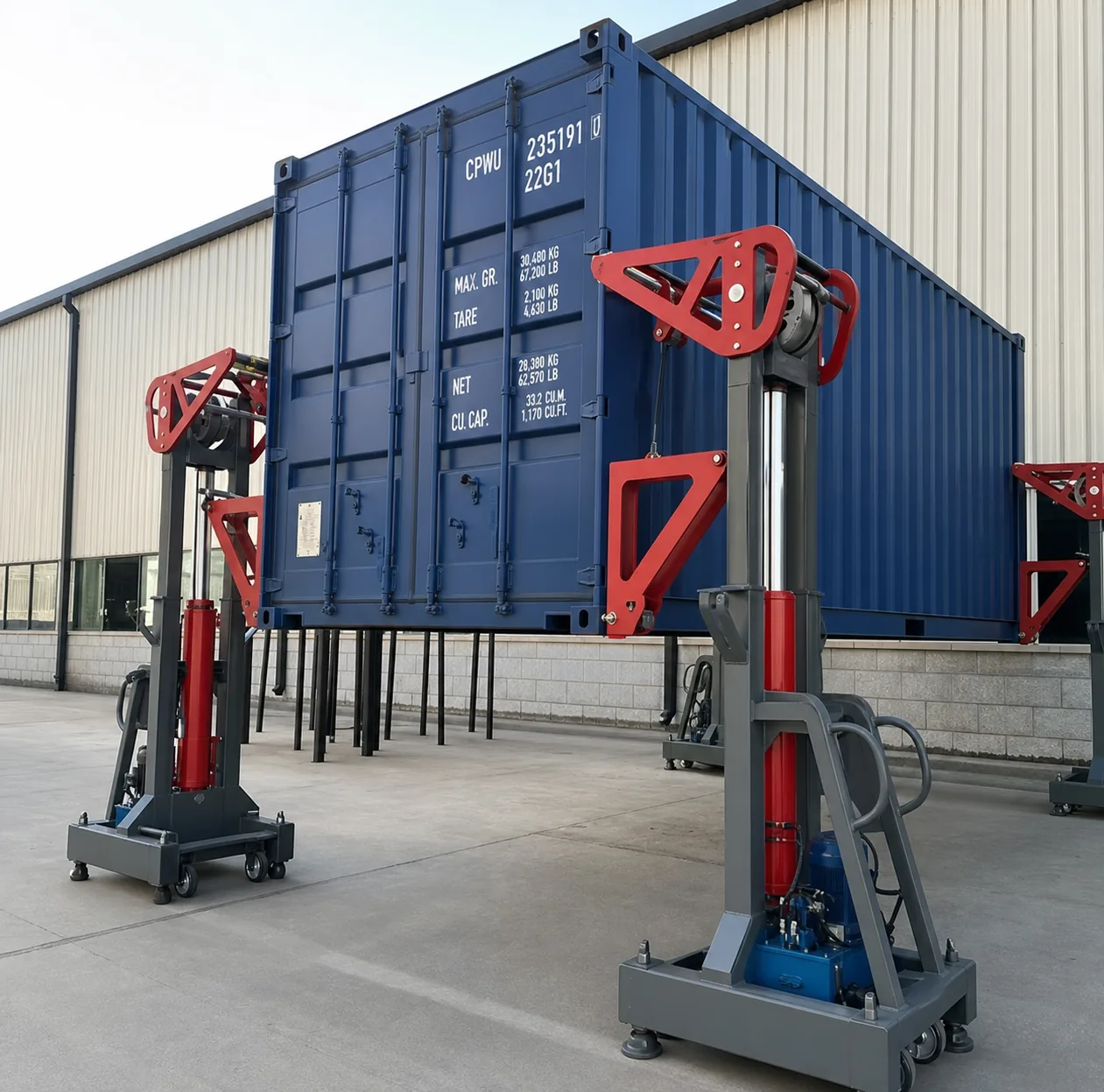
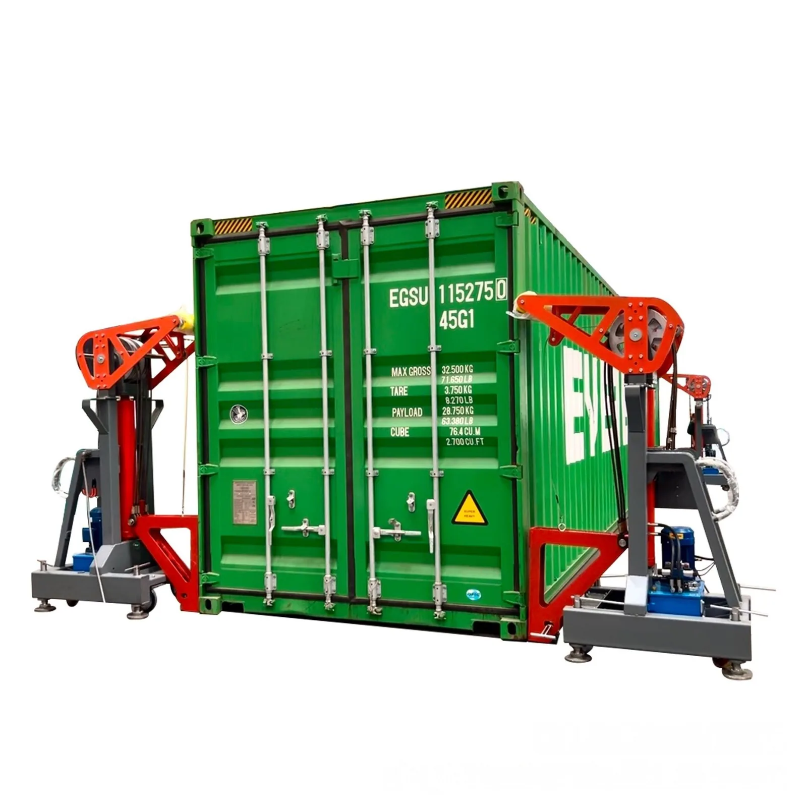
Four mobile container lifting units positioned around a freight container Cargo handling only
Project boundary: Product information is for application review only. Final suitability, operating procedure, supply scope and technical solution require project confirmation.
Potential customer savings

Illustrative annual operating-cost savings

Across three separate examplesUS$11,520–26,208 / year

Potential annual cost reduction. Select only the scenario that matches the buyer's current operation.

Frequent transfersIllustrative annual savingsUS$26,208/year

Potential cost reduction compared with crane use plus control labor.

Illustrative equipment payback: about 9 months
Ground loadingIllustrative annual savingsUS$18,240/year

Potential cost reduction compared with ramp use plus loading labor.

Illustrative equipment payback: about 13 months
Conditional forklift reductionIllustrative annual savingsUS$11,520/year

Potential cost reduction only where the local workflow can reduce forklift use.

Illustrative equipment payback: about 21 months

Use one matching scenario only; do not add the three values. Around US$20,000/set is an illustrative equipment-only reference for the 32 t standard configuration. These are not guaranteed savings or guaranteed payback. Freight, duties, installation and site costs are excluded; replace every assumption with the buyer's local costs.

Application fit

Start with the real workflow

This system is reviewed around how the container needs to move—not from capacity alone. Send the container gross weight, transfer direction, site and available clearance before discussing a configuration.
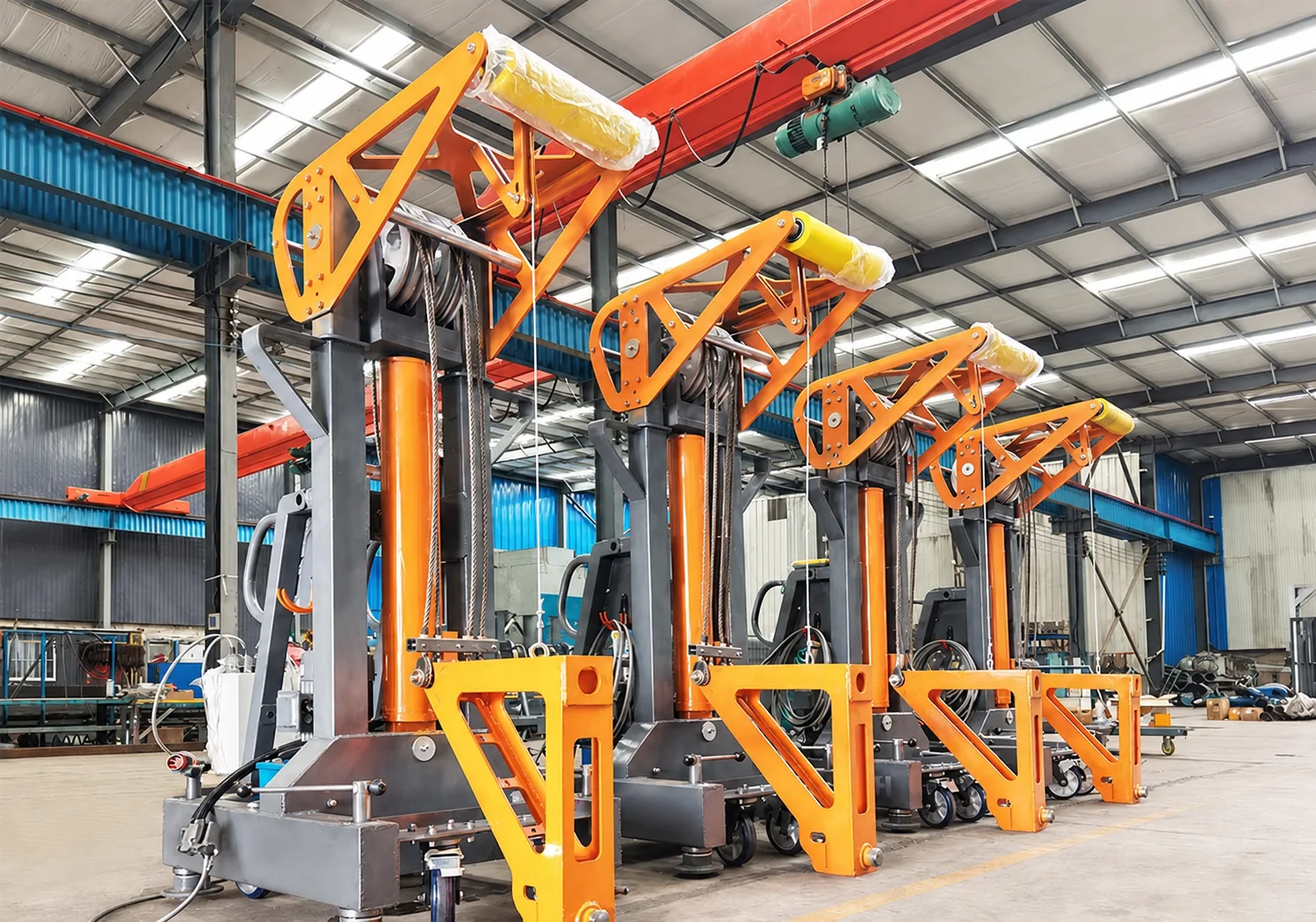
Four mobile lifting units arranged in a workshop
01

Container

Type, outside dimensions, empty or loaded condition, and gross weight.

02

Workflow

Truck-to-ground, ground-to-truck or another planned transfer sequence.

03

Site

Prepared support area, vehicle access, working zone and required clearance.

04

Utilities

Available power supply, voltage/frequency and expected operating frequency.
Real equipment arrangements

Application Examples

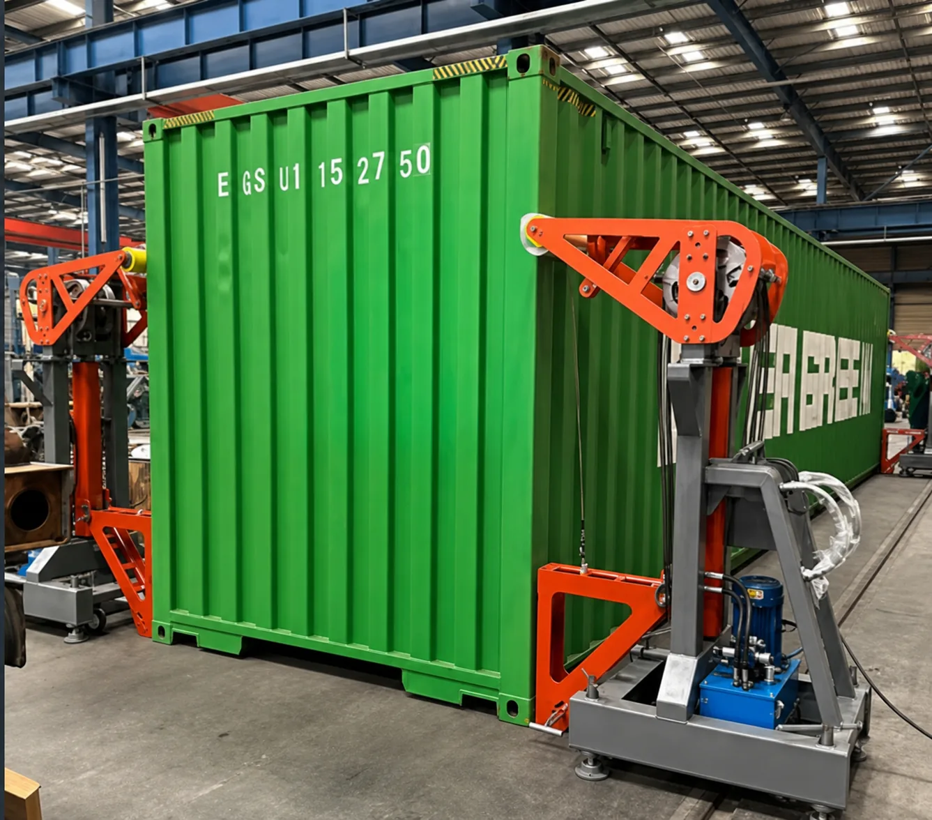
Indoor, outdoor and modified-container arrangements show how the four-unit system may be positioned. These are visual application examples, not verified customer cases, local installations or performance evidence.

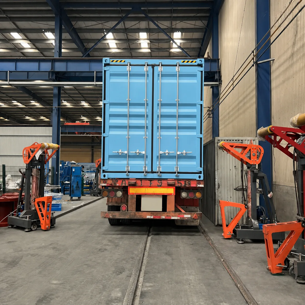
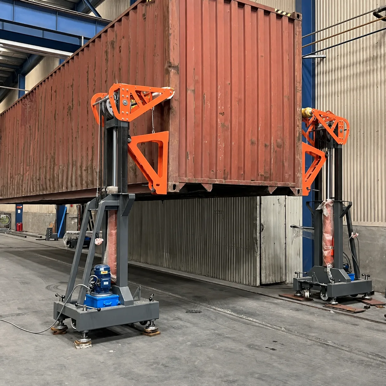
Indoor container lifting arrangement

Indoor arrangement

Four mobile units positioned around a standard freight container.

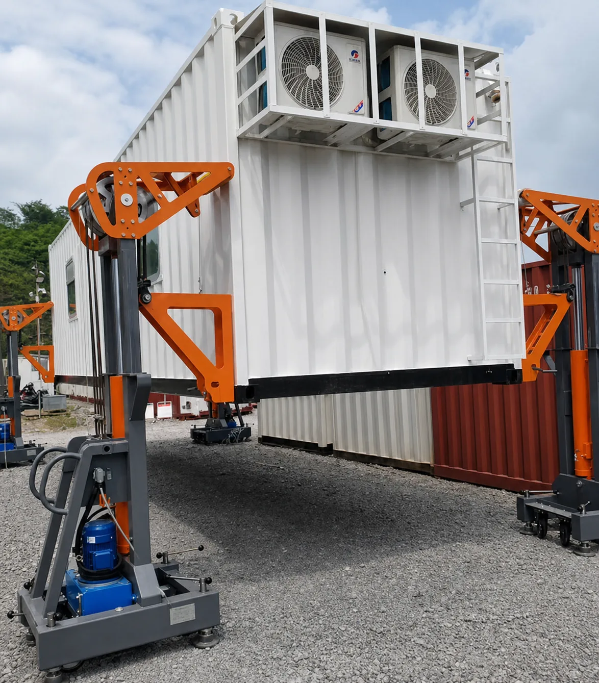
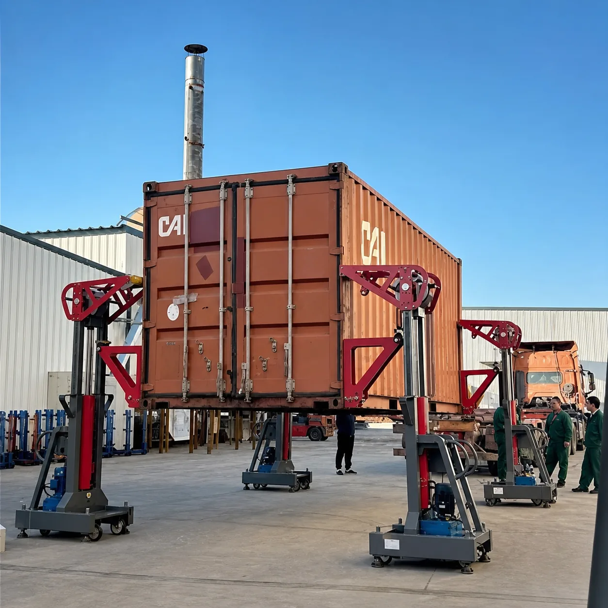
Outdoor container lifting arrangement

Outdoor arrangement

Site ground, clearance and environmental conditions require review.

Modified container format

Modified container format

Modified formats require separate suitability review before confirmation.

Standard configuration

32 t standard configuration

Four mobile lifting units, each rated at 8 t, form one 32 t standard set.

Four mobile container lifting units arranged as one set
Four-unit system 32 T RATED / SET

Four mobile units · 8 t rated per unit

Standard capacity 4 × 8 t = 32 t

One complete standard set

Power & remote
12 kW / setInstalled power for the complete set
3-phase 380 VProject voltage and frequency to be confirmed
Wireless remoteGroup commands and A–D individual jog
Travel & dimensions
1,650 mmMaximum / limit lifting travel
1,400 × 950 × 2,250 mmSingle-unit net dimensions
Net & packed weight
730 kg / unitEquipment net weight
830 kg / unitAfter single-unit wooden-case packing

Above 32 t: customized review only, up to 40 t maximum. 40 t is not the standard rated value, and custom component details are not published here.

Typical workflow

A clear, site-specific sequence

Only the clearance required for the planned vehicle movement is created. Exact steps, operator responsibility and exclusion-zone controls follow the approved operating plan and manual.

Mobile lifting units positioned around a container
STEP 01

Position

Place four units at the container corners on the prepared support area.

Lifting interface connected at a container corner
STEP 02

Connect

Attach the confirmed lifting interfaces and control/cable package.

Container raised to create vehicle clearance
STEP 03

Create clearance

Raise only the clearance required for the planned vehicle movement.

Container supported by four mobile lifting units
STEP 04

Transfer & lower

Move the vehicle clear as planned, then lower onto the prepared support area.

Equipment & control

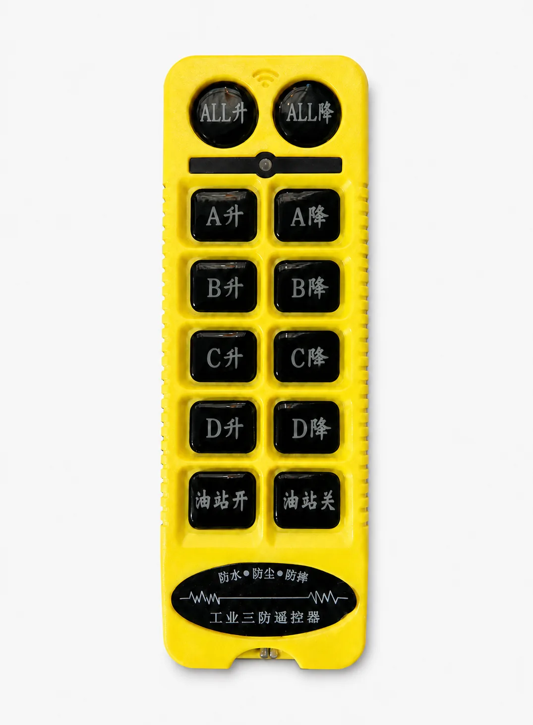
One wireless remote for group and unit-by-unit control

The four-unit set combines group commands for lifting and lowering with individual A–D jog controls for positioning and adjustment. Hydraulic-station start and stop are also available on the same handset.

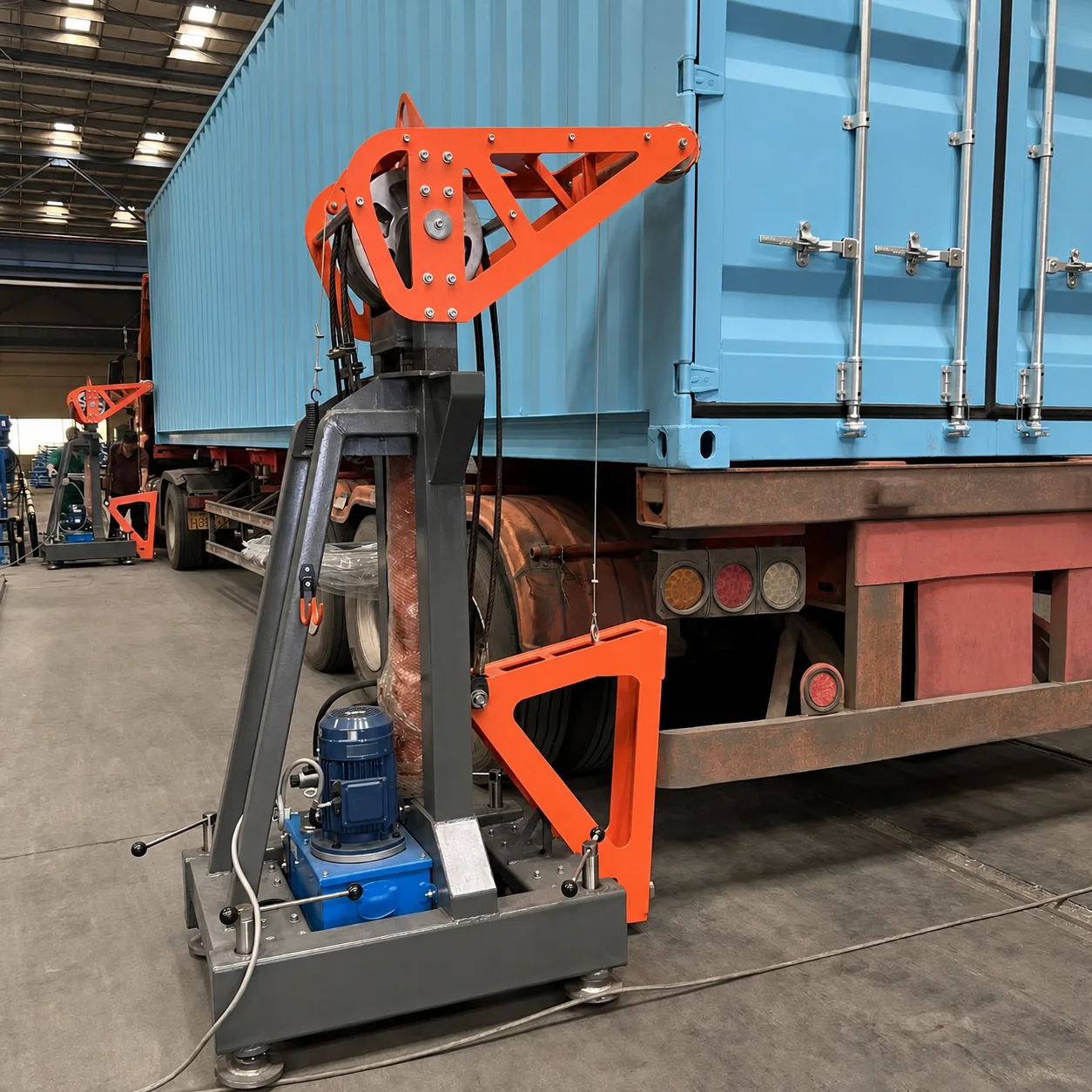
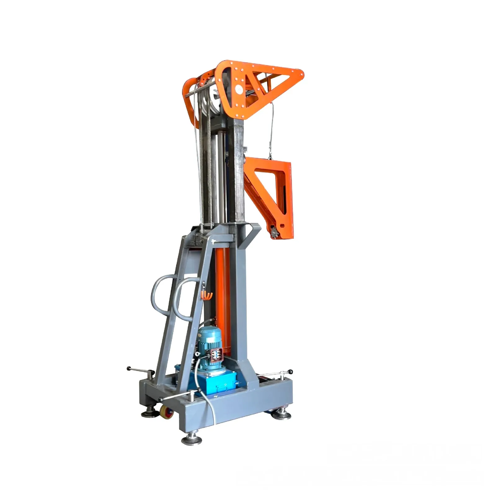
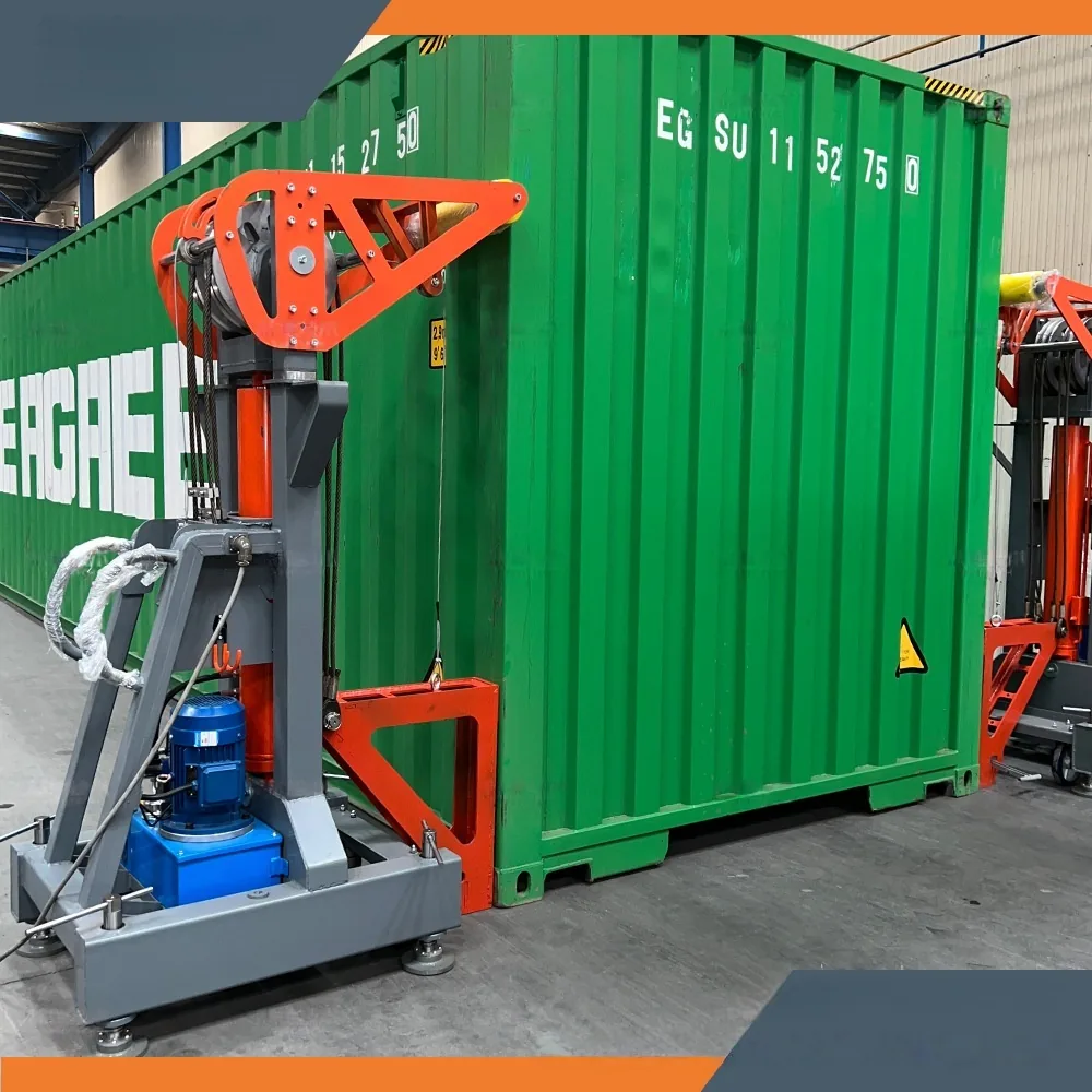
Single mobile hydraulic container lifting unit

Mobile hydraulic lifting unit

The mast, hydraulic power unit, caster base and adjustable leveling supports are integrated into one movable assembly for positioning around the container.

Wireless remote with group, A to D individual, and hydraulic-station controls

Group movement. Individual adjustment.

One portable handset combines the controls needed for the four-unit arrangement.

  • ALL UP / ALL DOWN — send lift or lower commands to all four units together.
  • A–D individual jog — raise or lower a selected unit during positioning and adjustment.
  • Hydraulic-station start / stop — control the oil stations from the same handset.

Control boundary: current evidence supports group commands and individual jog. Automatic synchronization, closed-loop leveling, safety interlocks, remote range and protection rating require formal documentation.

Site review

Ground, access and workflow first

Site photos or a short video are usually the fastest way to begin. Formal ground capacity and operating limits must be checked at project level.

  1. Container type, dimensions and loaded condition
  2. Firm, level support area and verified ground capacity
  3. Vehicle access and a clear working zone
  4. Available power supply and cable route
  5. Required lift clearance and transfer sequence
  6. Operator responsibility, exclusion zone and local rules
Mobile lifting units around a freight container
Packing preparation

Confirm the equipment list first

Final package count, dimensions, gross weight, securing method and destination requirements are confirmed for the order. They are not estimated from photos.

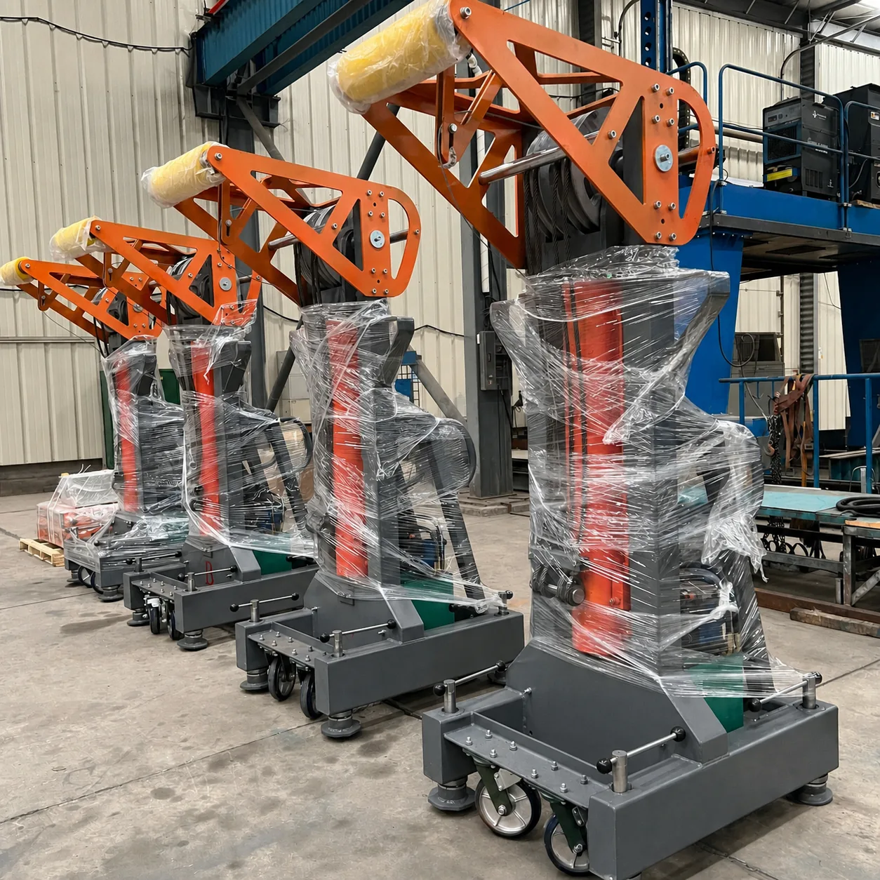
Protected lifting units prepared for packing

Protected units

Surface protection is applied before crating or loading.

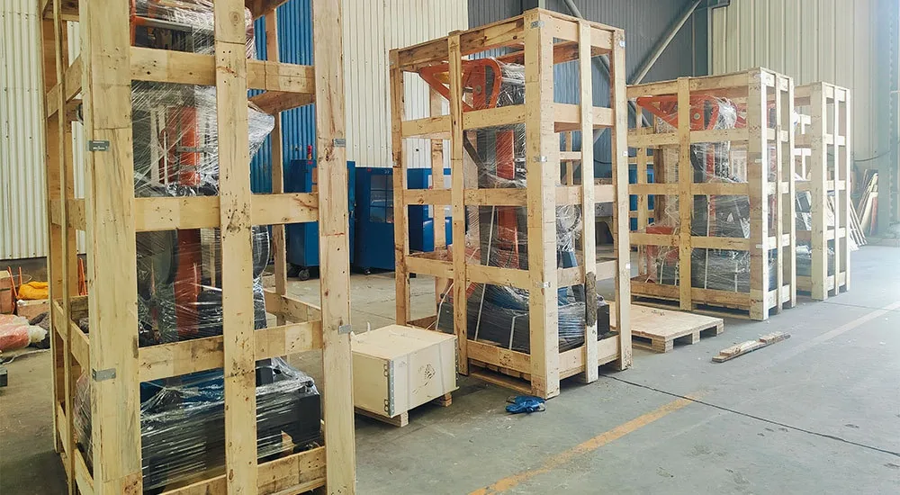
Individual wooden crates

Individual crates

The confirmed set and shipment requirements determine the crate plan.

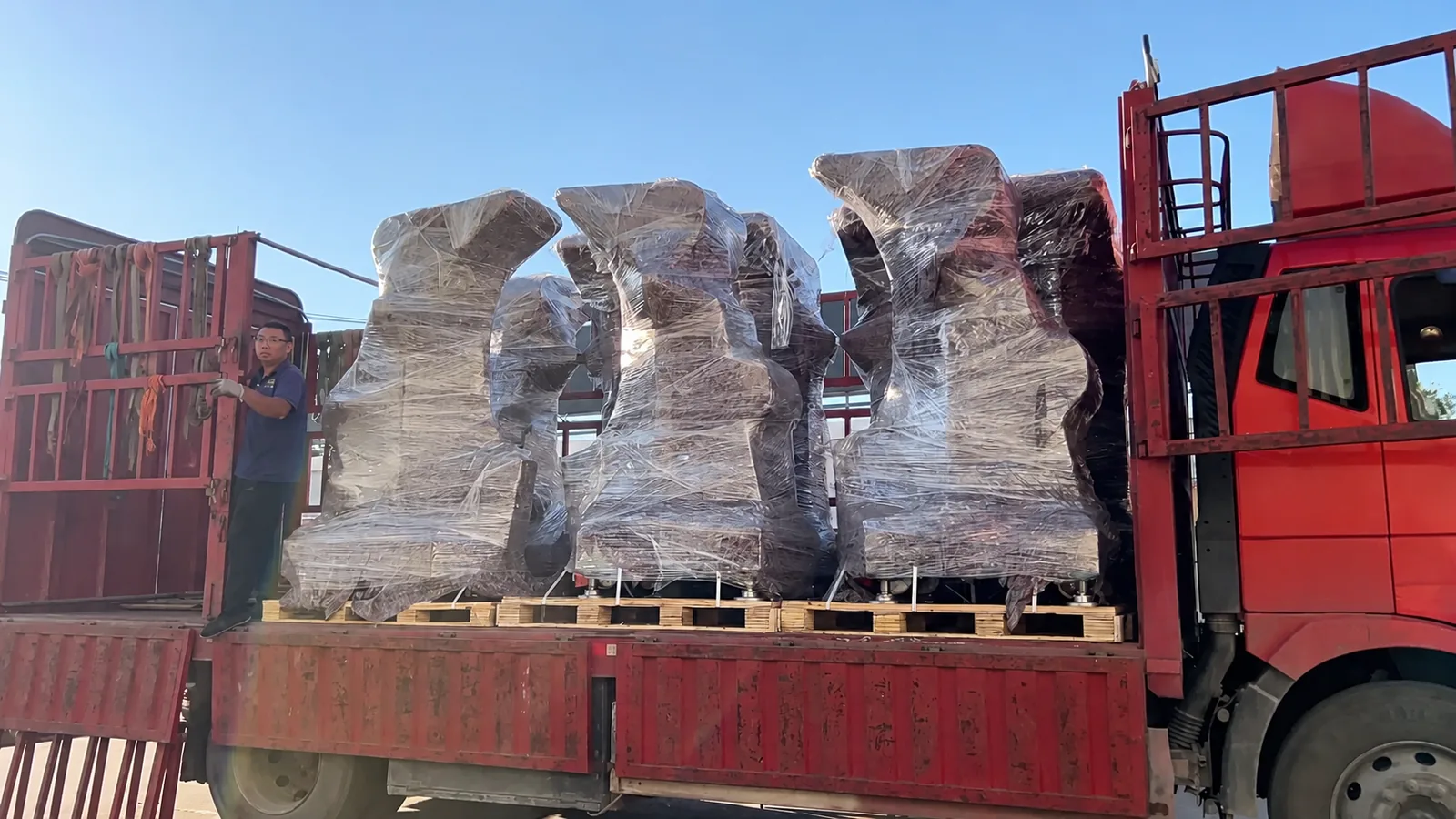
Equipment loading preparation

Loading arrangement

Handling and securing follow the final package data and route.

Project inquiry

Send the real application

We review the container, transfer sequence, site conditions and power supply before confirming suitability.

  • Container size and type
  • Gross container weight
  • Transfer direction or planned sequence
  • Site photos, ground condition and clearance
  • Available power supply
  • Destination and support required

Container lifting system inquiry

This form opens a prefilled WhatsApp message. You can send site photos and videos after opening the conversation. See our Privacy Policy.